As with all the previous weeks, I started this week with a fabacademy video on computer controlled cutting. The video broadly covered all the machines and tools that would be required for computer controlled cutting processes.
Some of the notes from the video are as follows:
- 2D cutting involved laser cutter and assembly models
- Some of the common knife cutters are a) Roland b) Zund c) Other cutter d) Ultrasonic (this one starts with a knife and moves to ultrasonic; it can cut through thicker materials)
- Some of the common laser cutters are a) Epilog b) Universal c) Trotec d) GCC e) Full spectrum f) Lasersaver g) 3D fablight h) Oxford i) Pharos
- Plasma is another type of cutter than is more affordable than laser, but it is often messier and dangerous a) Forest scientific b) Torchmate
- Waterjets can cut through almost any heavy material a) Frog wire b) Hot wire c) MTM
- Wire EDM is another type of cutter a) Sodick b) MTM
- The focus here in fabacademy is vinyl and laser cutter.
- The assignment requires students to focus on making a parametric cut
- Some of the popular 2D design tools are as follows: a) Inkscape extensions b) Rhino, with grasshopper c) Fusion 360, slicer d) Onshape e) Pepakura, Visicut, Flatlab, Exactpat (these are for art assembly) f) Blender, sverchok g) FreeCAD, Sketcher h) Solidworks x Design i) Antimony video
More on vinyl cutters:
- The assignment is to use the vinyl cutter to create a laptop sticker
- Applications a) Signs b) Thermal transfer c) pop-up cards d) origami, kirigami e) screen printing f) flex, multi-layer circuits g) antennas
- Materials that can be used for vinyl cutting a) knives b) vinyl c) masking tape d) transfer adhesive e) copper f) epoxy film g) sandblast stencil
- Important settings to keep in mind a) force b) speed c) cut depth d) temperature e) humidity
- Weeding - means removing the part you don’t want. This can be done using adhesive or lift v/s shear method.
More on laser cutters:
- The assignment is to use a laser cutter to create a pressfit construction kit. Try using FreeCAD.
- Applications a) marking, engraving b) modes include raster (moving back and forth), and vector (where light movement is drawing and heavy movement is a cut) c) screen printing
- Pressfit construction kits can be done with GIK, GIK.fcstd video, joints.jpg, joints.sb, stick-slip, bistable, pinned
- Important terminologies to keep in mind a) clearance b) chamfer c) parametric design d) parametric testing e) living hinges f) flexures g) mechanisms
- LASER stands for Light Amplification by Stimulated Emission of Radiation
- Important terminologies for LASER a) state diagram b) population inversion c) gain medium d) lasing threshold e) output coupling f) bean mode, profile g) diffraction limit
- Gain medium - CO2, fiber, Ingasp, Algaaas, Nd: Yah, T1 Sapphire, Excimer, Lifetime
- Cutting mechanisms - burning, melting, evaporation and albation
- Airflow - assist, exhaust, filter
- Kerf (refers to the width of the cut) - safety classes, venting, cleaning options, supervision, air/gas flow, fires
- Materials that can be used for laser cutting a) cardboard b) wood c) PMMA/acrylic/plexiglass/perspex/lucite d) POM/acetal e) [polycarbonate] f) [metal] g) flame test
- Important settings to keep in mind a) power b) speed c) rate d) coordinate system e) origin f) vector, raster
For the week’s assignment, try to create living hinges, kerfing, try to create an object with a curve.
For this week, I thought I’d first try to put together an origami using either the vinyl cutter or the laser cutter.
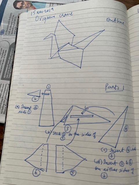
I made an origami crane on a piece of paper. It was beautifully proportionate. Richard then suggested I design the same online and assemble the different pieces together. To understand how to use inkscape to design an origami crane, I first broke down an origami crane into multiple parts – so each part can fit into another and create a full crane. The diagram below shows the drawing I made on paper.
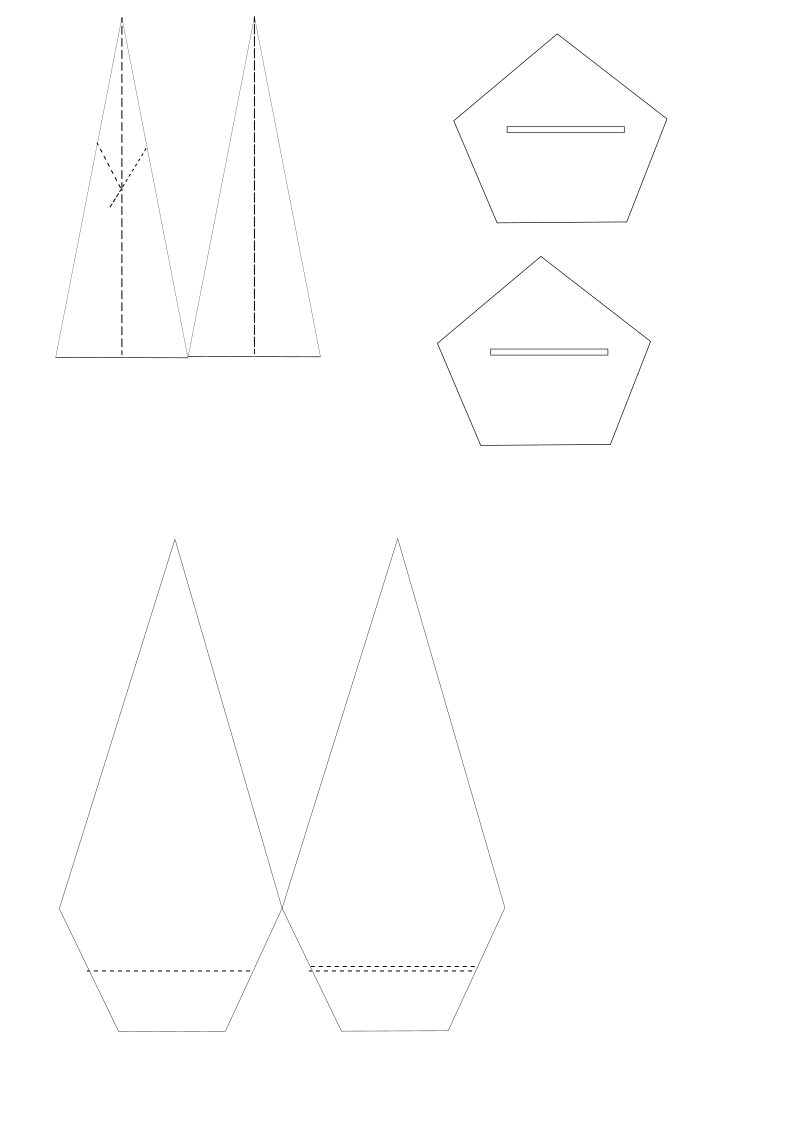
I then tried to replicate this on Inkscape. For the trial round, I decided not to use any dimensions per se – the sides were arbitrarily measured and drawn.

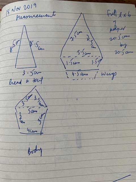
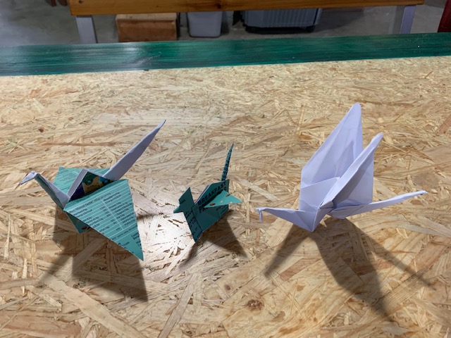
I then drew out similar patterns on a piece of food packaging cardboard (need to check with richard on the strength of the packaging material and what it is made of). Here again I drew them out arbitraility without any measurements, and cut them using a pair of scissors. As I hadn’t measured out the individual parts, the crane was completely disproportionate (middle crane in the picture below). I then measured the initial origami crane I had made on paper, and measured each of the sides using a ruler. I noted down the measurements. I also realised that for the cardboard box strength I was using, three parts were sufficient to create an origami crane – a triangle (for head and tail), one hexagon (for two wings), and one hexagon (for two sides of the body).
Even for the one with dimensions, measuring on paper and recreating the design on Inkscape was not so straight forward. For instance, for the triangle, while I had the sides of the triangle, that was insufficient for me to create the triagle itself, because the dimensions on inkscape showed me only height and width. So using the length of the base and the sides, I had to roughly calculate the height of the triangle and draw it out on Inkscape. Same for the hexagons. M suggested using and applying trignometric ratios to calculate these lengths. I also need to check with Saali to see if there’s any other way of doing the dimensions.
This created a much more proportionate origami crane.
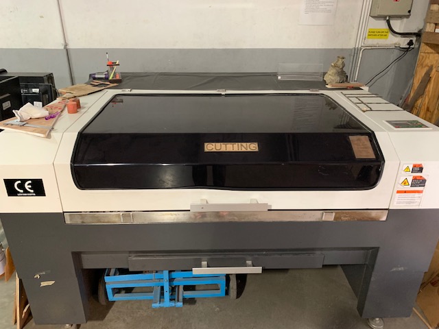
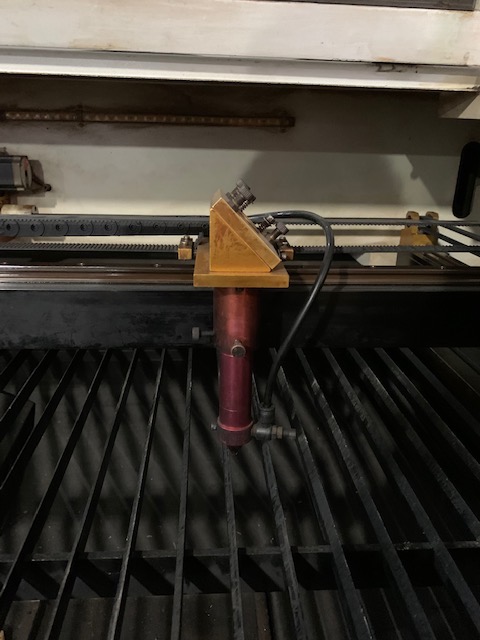
After the crane exercise, Richard took me through the laser cutters that we have here and showed me the specifications on these machines and how they work.
Laser cutter
- 80W CO2 laser glass tuber
- Chinese cutter
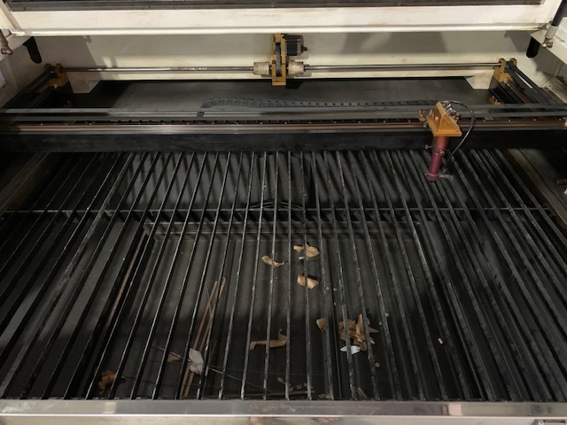
- BEd size is 4ft by 3ft - with metal blades (made of Mild Steel or Stainless Steel) - usually the bed size is more than this area indicating that a material of these dimensions can fit in comfortably.
- There’s a separate waste collection tray
- The idea behind the manufacturing of this laser cutter is to keep it as low cost as possible. It costs anywhere between INR 4-5 lakhs.
- It can’t cut metal - mainly used for cutting acrylic.
- Software: Thunderlaser (free) - MAC seems currently incompatible with laser cutting files. I could not open a file for laser cutting on the mac.
- Files should be saved as DXF files - Digital Exchange Format
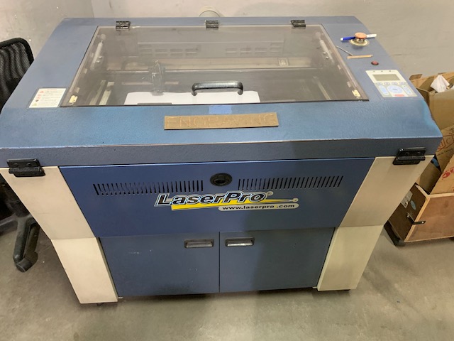
Laser engraver (can also called a laser cutter)
- Laser pro - spirit family model
- Manufactured by GCC company - it’s an American machine
- Bed size is 18 inches by 29 inches
- CO2 laser metal tube
- 25W
- It can’t cut metal - mainly used for cutting acrylic.
- DPI - Dots per inch (useful for engraving)
- PPI - Power per inch
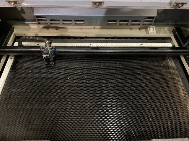
- It has a moving bed to control the quality of cutting or engraving
- Software used: Coreldraw (who have partnered with GCC)
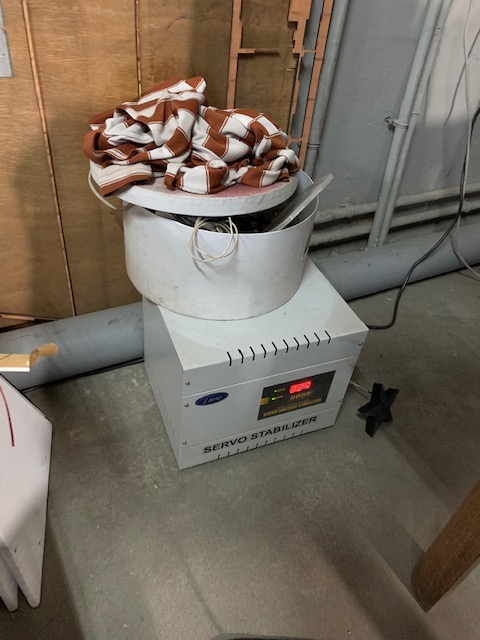
Both the cutter and the engraver are connected to a voltage stabiliser. They can be controlled via a USB cable (for info & power data.)
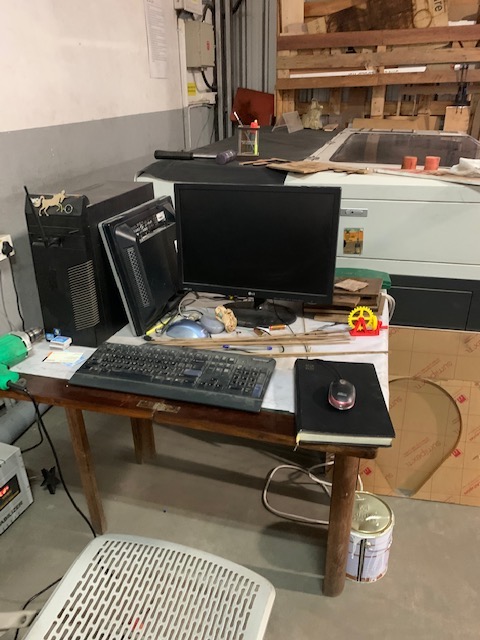
Apart from these, there is a design computer, where I can save my designs and feed it into the engraver and cutter.
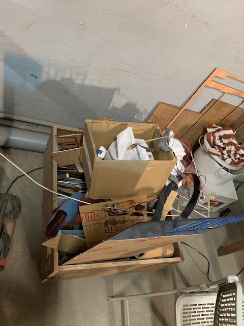
The workshop has a collection of scrap materials that can be used for the exercises where we use these machines.
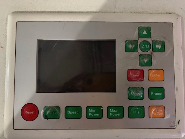
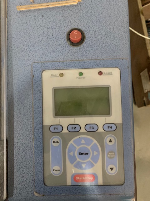
When you switch on either machine, it calibrates on the bed. For the engraver, the head checks the length, breadth, and diagonal and comes back to home. For the cutter, the head moves back to the last position it was at before the machine was switched off.
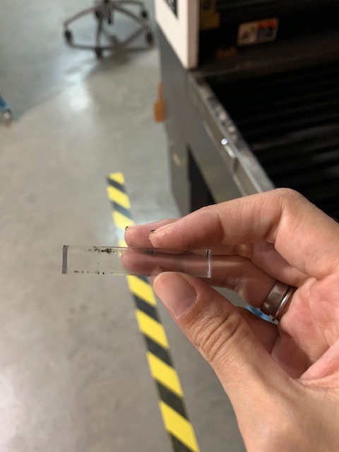
After explaining the basic working of the cutter and the engraver, I downloaded a DXF file from thingiverse – a pressfit construction kit snail. I used a design by OBUQ from Thingiverse, August 26, 2017. While the design downloaded on my laptop, the file did not open on the laptop – I couldn’t figure out the reason (it is likely a MAC issue). We then downloaded it directly onto the design computer connected to the laser cutter, and printed it out. While the blog suggested the use of 3mm MDF, Richard suggested we try using acrylic. Here’s what the laser cut snail looks like. It’s so beautiful!
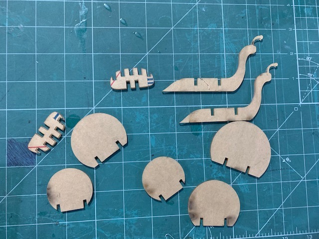
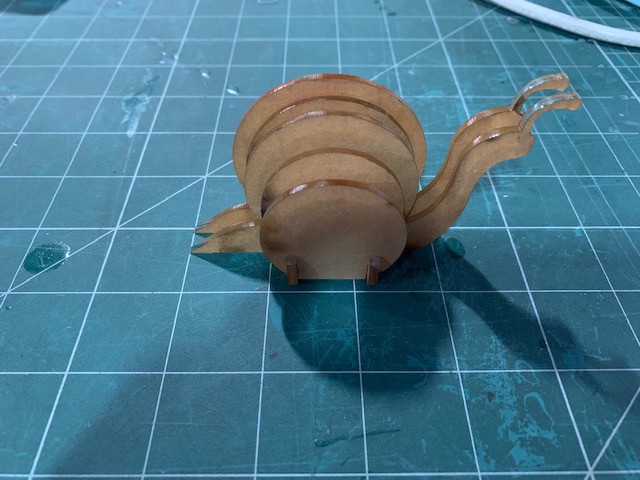
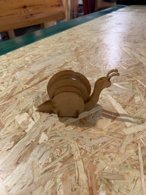
In a typical press fit construction kit, the pieces will have to fit into each other neatly without the need for any adhesive. However, in the case of the case, some of the parts come off the whole quite easily. I think this could be for two reasons: 1) material used – while the thingiverse page suggested the use of 3mm MDF, we used acrylic, maybe MDF would have held the pieces together more snugly?, 2) design flaw - it could be that the joints could have been more tightly (lesser width) designed. We can conclusively say this only if I make modifications to the design, and try cutting them out again.
For the snail project, I used another maker’s design to understand the things I have to keep in mind while designing a pressfit construction kit. As a next step, I designed my very own tree pressfit construction kit. The following picture was a rough paper sketch of what I wanted the tree to look like.
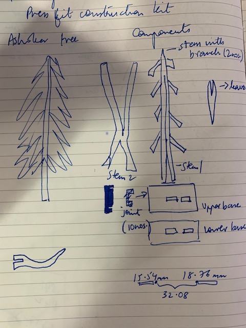
Similar to the crane and snail exercise, I divided the whole tree into individual parts and designed the following parts: 1) Base (to hold the trunk with branches and leaves, 2nos.), 2) trunk with branches, and 3) leaves
I designed these parts on Inkscape. For the joints, I decided to go with a 5.2mm width. Before beginning my design, Salih suggested that I keep two things in mind while designing, 1) Material width (so the places with the joints have the same measurements as the material width) 2) Machine tolerance or machine error - so if we have to cut at 53mm, we cut at 53.1mm to leave a margin of error for the machine.
Keeping these two factors in mind, I worked with a block of 5mm MDF wood. However, when I measured the width of the 5mm MDF, it was actually 5.2mm thick.
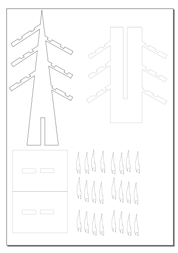
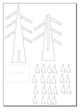
The following is the tree design I initially made.
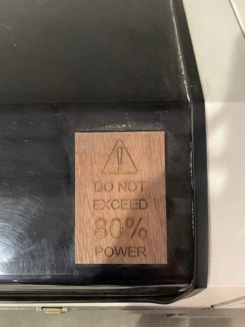
Once I completed the design, I saved the file as a .dxf file (Digital Exchange Format), saved it on a pendrive and opened it on thunderlaser software in the design computer at the workshop. On Thunderlaser, Salih suggested that, based on the material and the design, we set a power of 80% and speed of 10%. Since the design computer could not be connected to the laser cutter directly. We copied the settings onto a USD drive and inserted it into the laser cutter. This is the first cut of the tree parts.
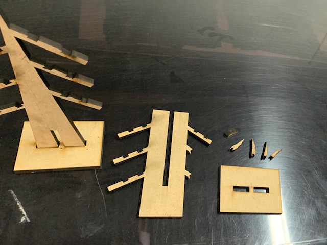
It is only after fully cutting the tree out did I realise that the leaf width had inadvertently modified to 3.1mm, instead of 5.2mm. This means that the leaves would not fit onto the tree. The reamining parts did. However, because of the width of one of the trunks, it lacked structural integrity to hold the branches and that broke easily as well.
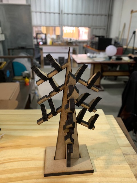
So I redesigned the second trunk, and the leaves, ensuring that the measurements lined up. This time, for the leaf, I took a width of 5.3mm, and on cutting this out on the board, it fit in perfectly this time.
Here is what the second design looks like on Inkscape.
Here are pictures of the ashoka tree as a fully put together pressfit construction kit.
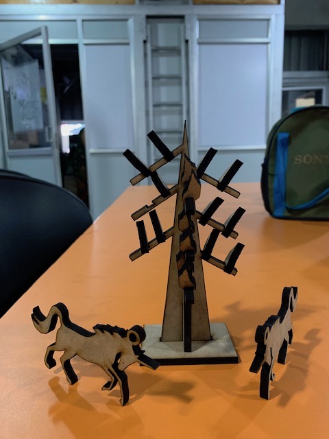
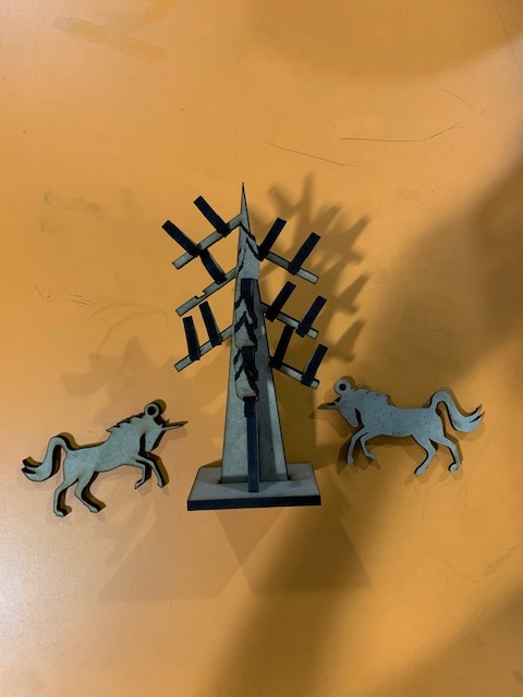
[The stallions in the pictures above were not designed by me; they were designed and laser cut by Salih.]
Here is a video that shows how the parts are joined together neatly without an adhesive, and simply by joining together. They do not fall apart when you turn them upside down. That’s a win!