After the excitement of 3D scanning and printing, I returned to electronics. This time, instead of working on a ready-made Arduino kit, we worked on circuit boards and printed circuit boards (PCBs).
I first completed the Fabacademy video on Electronics Design.
The video covered two main aspects:
- Components that go into a circuit board
- Logic that one has to apply and the softwares that can be used to create a digital circuit board that can then be easily printed for use.
Components
- Inventory
- Wire
- Button
- Switch
- Resistor: I = V/R
- Capacitor: C = Q/V, I = C. dV/dT a) Unpolarised b) Polarised
- Crystal, resonator
- Inductor: V = L dL/dT
- Diode: Current from anode to cathose a) PN b) Schottky c) Zener d) LED
- Transistor a) Bipolar: Collector, emitter, base current gain b) Mosfet: Source, drain gate, resistance
- Battery, regulator
- Op-amp: differential gain, negative feedback
- Microcontroller
- Sensors
- Actuation
Circuits
- Kirchoff’s laws: sum current at node, voltage around loop = 0
- Power: P = I^2R = IV
- EDA [This is CAD for electronics.]
- Hierarchical, parametric drawing
- Packages, footprints, libraries
- Schematic entry, component placement, (auto) routing, simulation, fabrication
- Design rules
- Routing layers, power planes, ground power
- Drawing
- Drafting tape
- Circuits, virtual breadboard, fritzing
- KiCAD video
- Eagle, Fusion 360
- Libraries, Digi-key, Snap EDA, Ultralibraries
- Design spark, Multi SIM, BLUE
- Atrium, Circuit Maker, PCB
- OrCAD, Cadence, Synopsys, Mentor, Tanner
- SPICE, LTSpice, Ngspice, gSpiceUI, Magic
- GNUcap, QUCS, Oregano, Multisim, Falstad
- Verilog, VHDL
- Kokompe, Kokopelli, pcb.py video
Test equipment
- Digital vottmeter
- Oscilloscope
- Regulated power supply
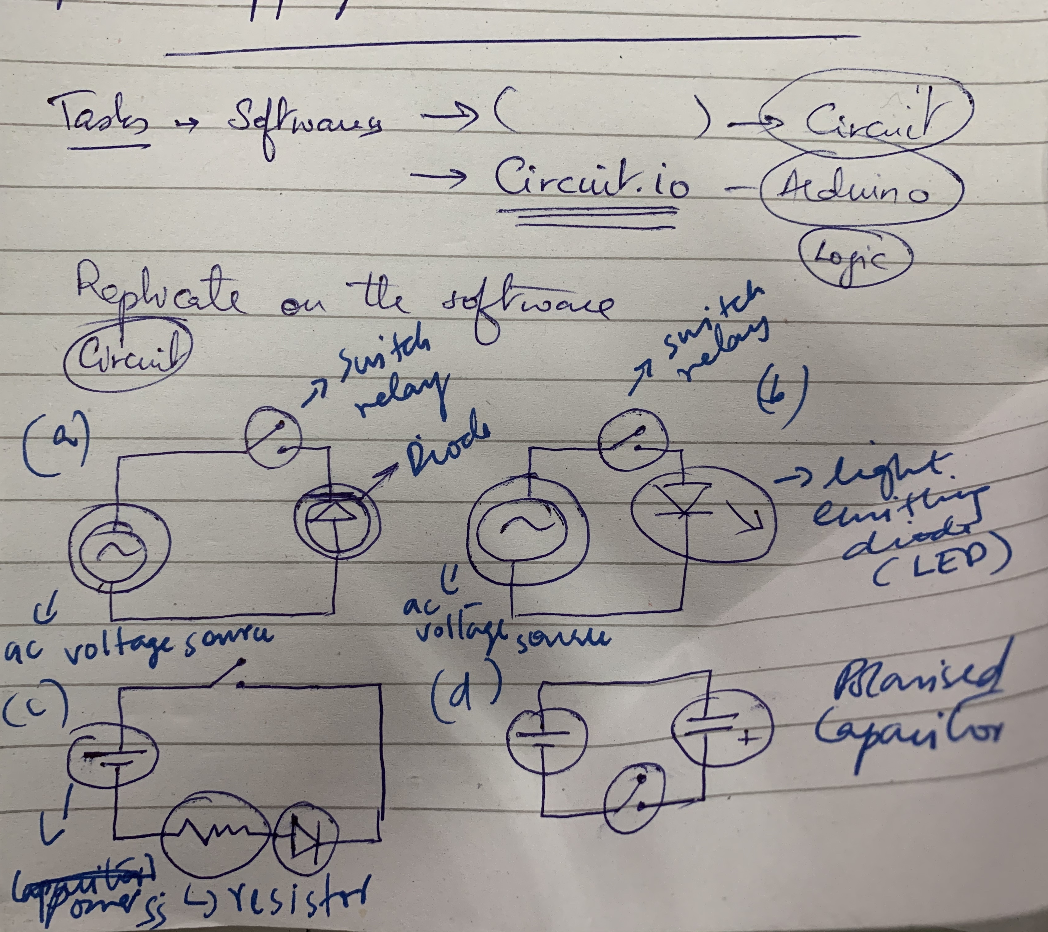
After watching the video and understanding the basic components and softwares that can create circuit boards, Richard then drew out some basic circuits on paper, for me to replicate on any software I choose to use.
These are the circuits that Richard drew out.
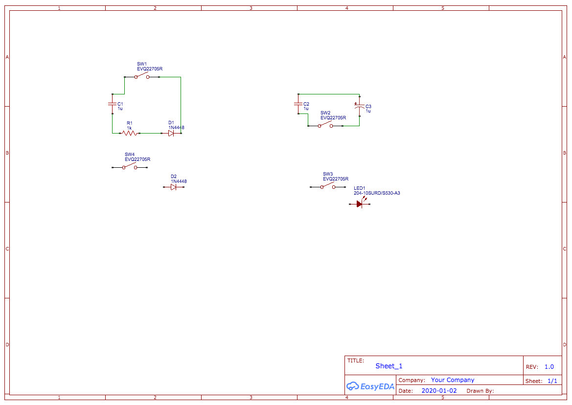
This is what I replicated digitally using Easy EDA. I chose to use this software after reading Richard’s blog where he had also used this software. He had written that this was a simple tool to use for someone who does not have much of a background in electronics.
After this basic exercise, Prageeth from Yuva impulse showed me what a PCB looks like and how it is created. While Arduinos are typically used for robotics, and need to be connected with a laptop or PC to work, PCBs can work independently since they are already programmed.
A PCB consists of a base made of fibreglass, with a copper coating on top. Once you design a circuit board, you print out the design and paste it on top of the copper. Once you apply heat (etching process), the design will stick to the board. You then clean it, make holes and place the components in the appropriate places on the board.
We then worked on a few exercise kits that Yuva impulse uses for the schools that they work with.
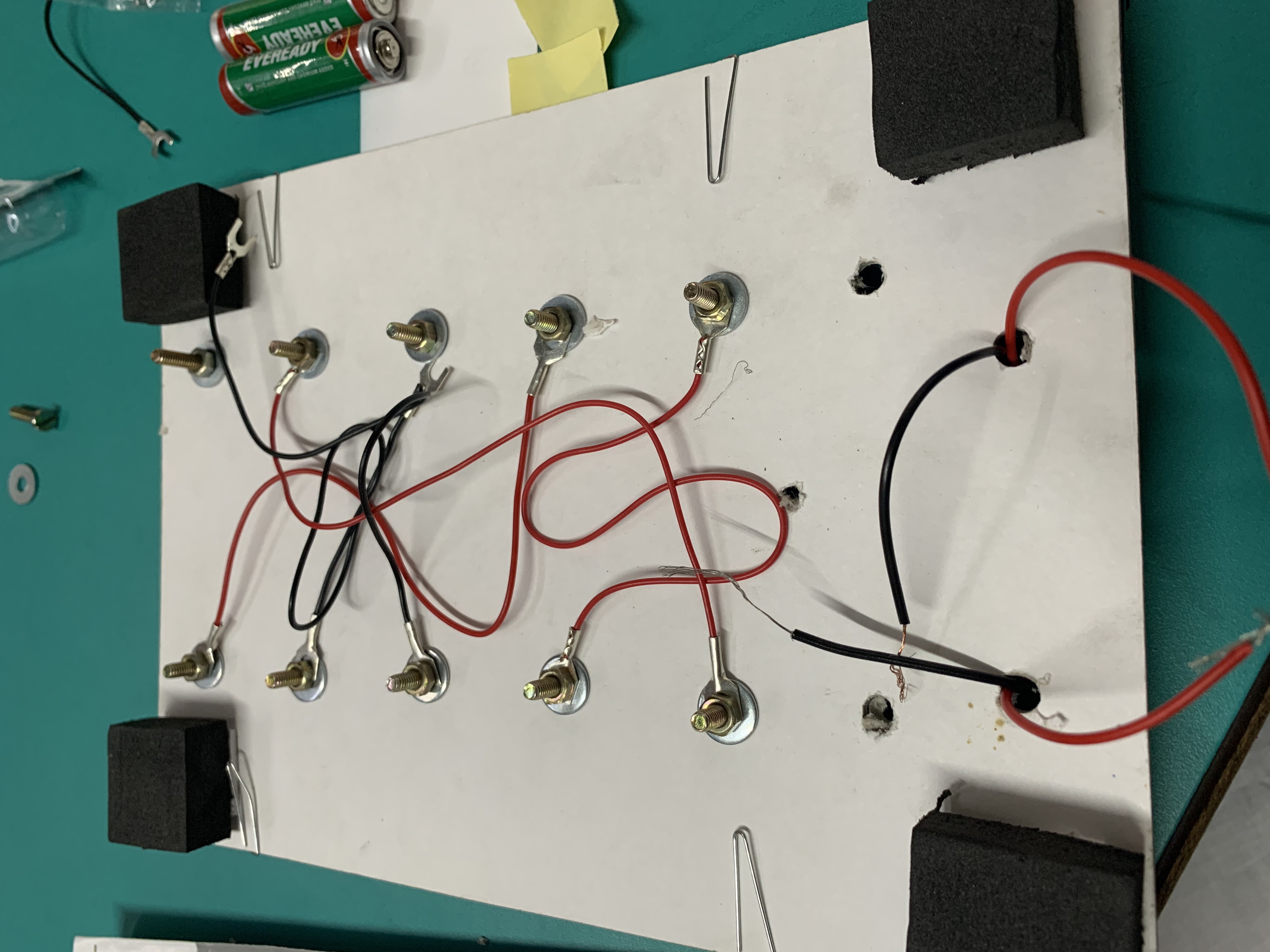
Exercise 1. Match the parts.
Left side has birds and right side has their feet. With the exercise, I had to put in the right connections behind the board, and then when connections are made on the front of the board – the buzzer will ring and LED will come alive if the right items are matched. Here is what the back of the board looks like.
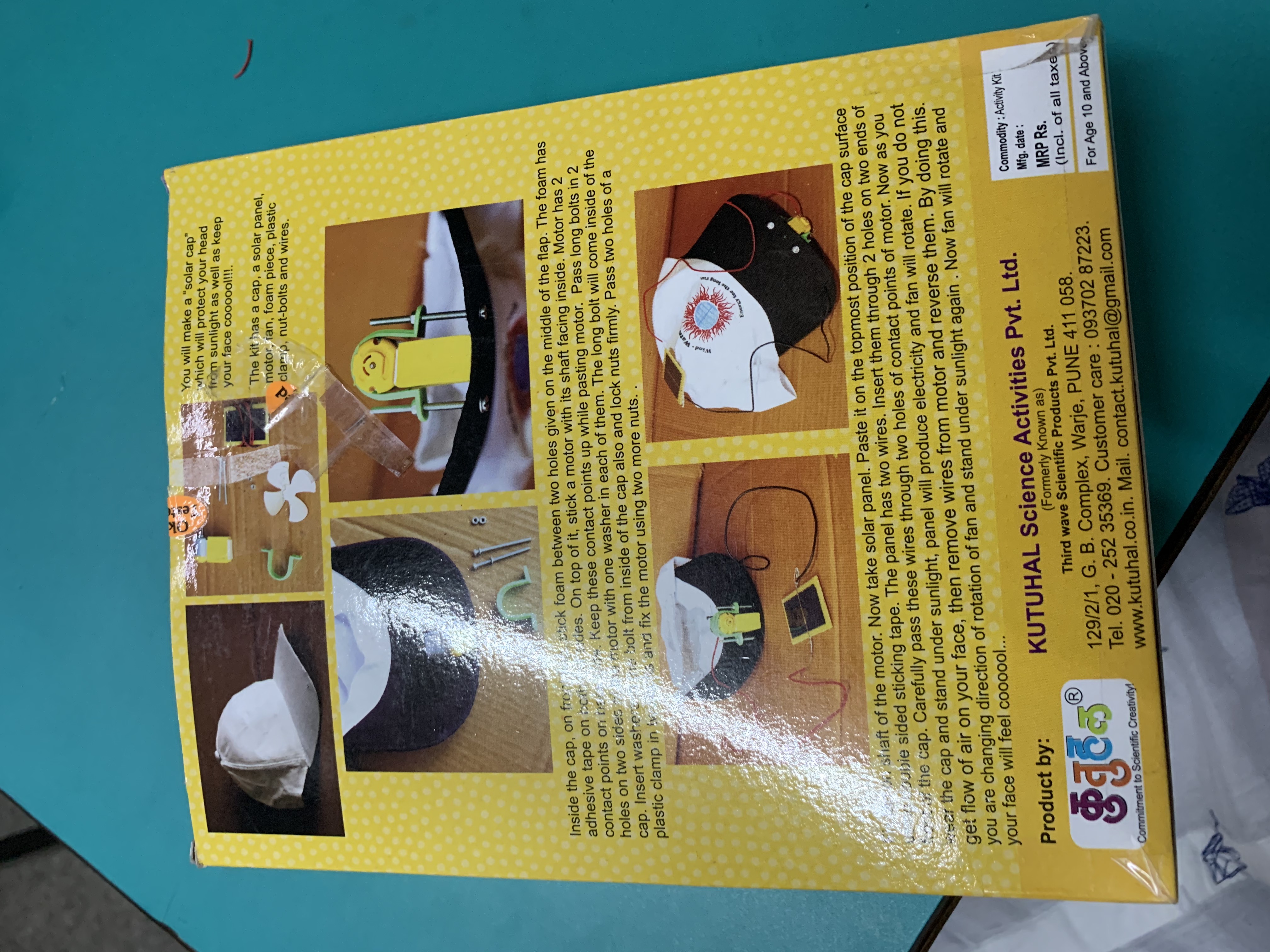
Exercise 2. Solar powered fan cap
This was a really interesting project. With this kit, I assembled the components available in the kit to create a propellor in a cap that powers itself using solar energy.
These are the components that go into the kit.
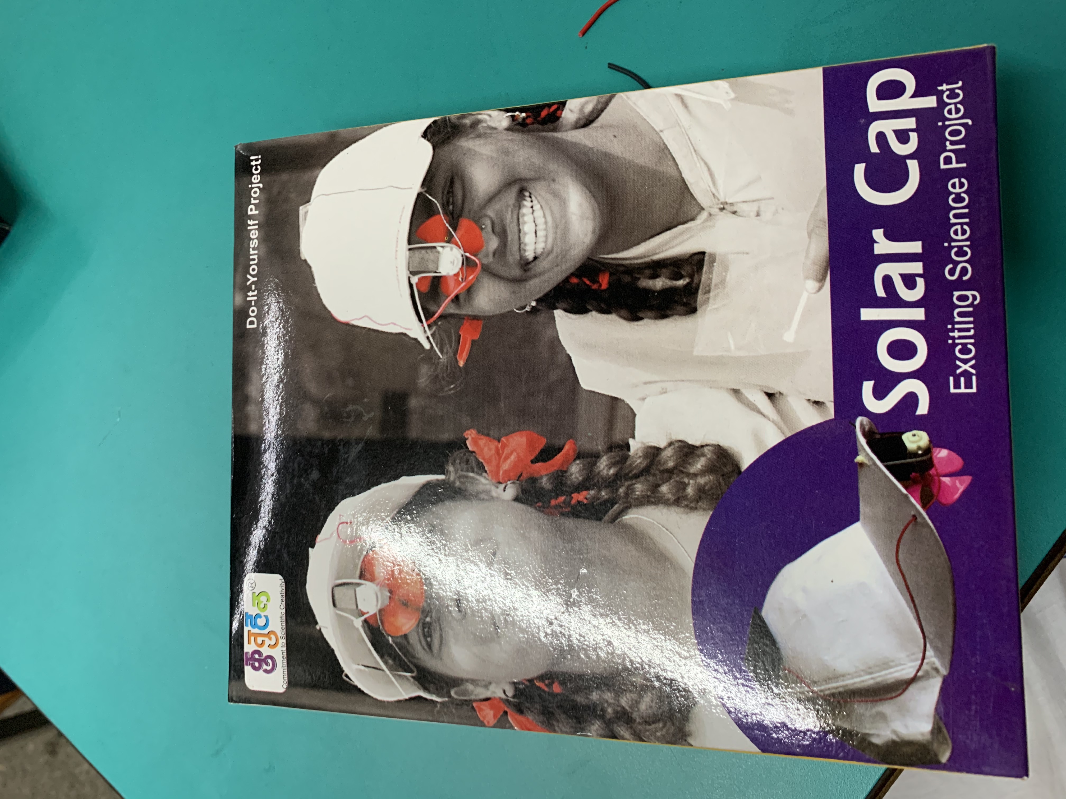
Here’s what the cap looks like when fully assembled.
Exercise 3. Electromagnetic bell
Here, I put together the components to power a hammer that will hit a bell – much like how a door bell rings. However, in this, the connections did not align as well as it should so it vibrated a little when I put it together, but did not ring fully.
Here is what the assembled kit looks like.
To understand the different components of a circuit board and how to design them digitally, Richard suggested I take one of my project ideas, find the relevant circuit boards online for designing.
I found a project online for an automatic drip irrigation system on electronicsforu.com. I want to set up a similar system at home so I can water the plants remotely while travelling, without requiring external help and at the same time without flooding the garden area.
This is the circuit that I created.
I spent atleast eight hours working on this – I’m mentioning this only to show that the complex circuit designs like this one need to be designed carefully.
As an exercise, I designed some more circuits on EASYEDA based on existing designs I found online. These include:
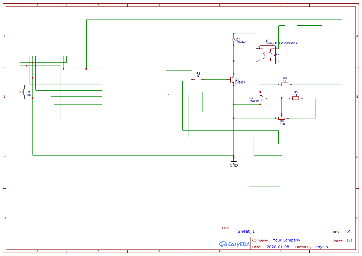
Design 1. Remote control for home appliance
Source: Found on electronicsforu website
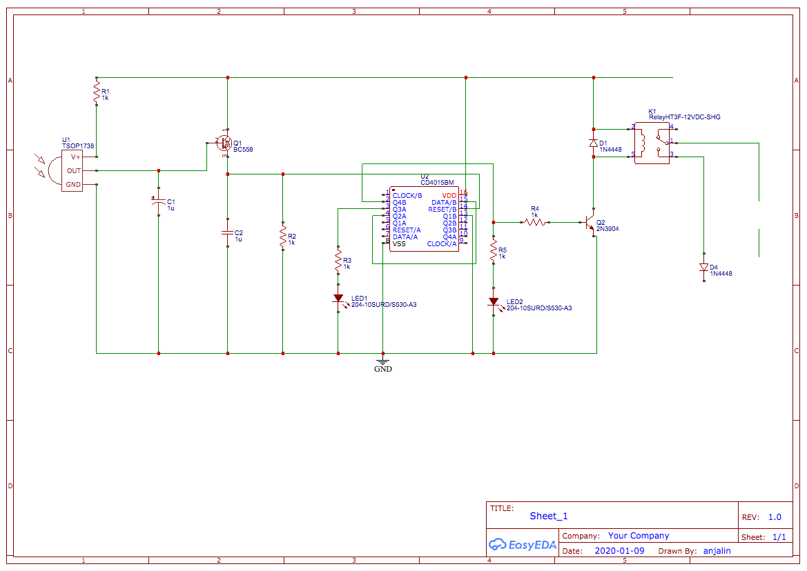
Design 2. A PIR motion detected light sensor
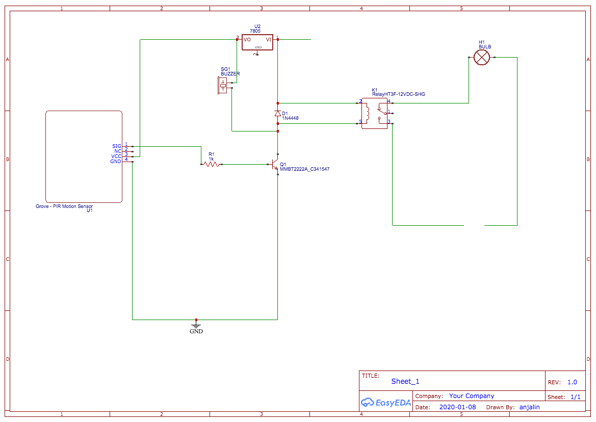
Source: Found on circuitsedia website